TM 1-1520-238-23
5-230
Change 9
5.51.
TAIL ROTOR ASSEMBLY INSPECTION – continued
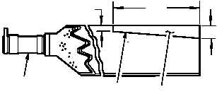
(4) Check tail rotor blade (2) erosion strip (18) for
bonding separation. No debond allowed.
(a) Visually check for cracked paint or raised
seam at edges (19) of erosion strip. Use
10X magnifier as necessary to assist in-
spection of erosion strip bond line.
(b) Coin tap any suspect area of erosion strip
(18). Tapping alternately between a sus-
pect area and a bonded area will produce
a different sound. A dull sound (thud) will
indicate a debond. A properly bonded
area will produce a sharp ring or solid
sound.
(c) If debond is suspected but cannot be
confirmed by visual or coin tap inspec-
tion, perform NDI dye penetrant inspec-
tion (TM 1-1520-264-23).
(5) Visually check tail rotor blade (2), and tip cap
(11) for loose or missing screws. None al-
lowed.
(6) Check tail rotor blade dust shield (10) for
splits, tears, or deterioration. None allowed.
i. Check electrical conduit (12) and receptacle
(13)
for
loose
attachment
(TM 55-1500-343-23).
j. Check bumpers (14) for loose attachment,
wear, splits, or deterioration. None allowed.
k. Check torque of tail rotor attaching nuts (15).
(1) If torque is less than 750 INCH-POUNDS (be-
fore MWO 1-1520-238-50-46), 710 INCH-
POUNDS (after MWO 1-1520-238-50-46),
remove tail rotor fork assembly (para 5.60).
l. Check drive links (scissors) for axial play.
(1) Load-bearing maximum allowable axial play
0.030 INCH measured at the elbow joint.
m. Check drive links (16) for loose attachment.
None allowed.
n. Check pitch control links (17) for loose attach-
ment. None allowed.
GO TO NEXT PAGE
18.0
2.0
M04–2006–4
2
18
19
1.0


