TM 1-1520-238-23
Change 7
5-256.7
5.57A.
TAIL ROTOR HUB ASSEMBLY REMOVAL/INSTALLATION (AVIM) – continued
(a) Allow primer to cure for 30 MINUTES at
room temperature.
(9) Apply sealing compound to threads of bush-
ings (20). Use brush (item 34, App F) and
sealing compound (item 168, App F).
(a) Allow sealing compound cure for 40 MIN-
UTES at room temperature.
NOTE
Threaded bushings should be evenly
started in hub until finger tight.
(10) Install threaded bushings (20) finger tight in
hub (6).
(11) Insert bolt (11) through bushings (20), hub
(6), and strap pack (10) for alinement.
(12) Alternately tighten each threaded bushing
(20) until final torque of 40 to 60 INCH-
POUNDS is reached on each bushing (20).
Use torque wrench and torque adapters sup-
plied in centering kit.
(13) Check for equal clearance between gage
block (21) and spare bolt (22) at each end of
hub (6). Use thickness gage.
(a) Strap pack must be within 0.005 INCH of
each end of hub (6).
(14) Remove bolt (11) from hub (6).
(a) Bolt (11) must move freely in hub (6),
bushings (20), and strap pack (10) during
removal.
(15) Seal notches in threaded bushing using seal-
ing compound. Use sealing compound
(item 156A, App F).
c. Inspect (QA).
d. Remove four thickness gages, two spare
bolts (22), and two gage blocks (21).
e. Remove hub (6) from V-blocks (16).
(1) Remove four thumb screws (17), two clamps
(18), and hub (6) from V-blocks (16).
GO TO NEXT PAGE
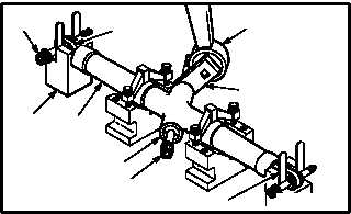
TORQUE ADAPTER
TORQUE WRENCH
20
11
6
21
22
M04-3245-4
THICKNESS GAGE (TYPICAL 4 PLACES)
10
THICKNESS GAGE (TYPICAL 4 PLACES)
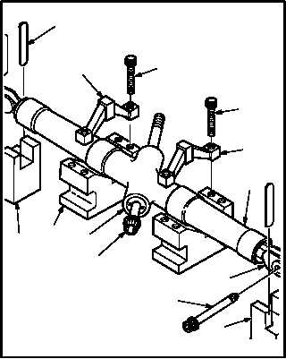
18
17
21
16
20
11
10
22
21
17
18
6
M04-3245-6