TM 1-1520-238-23
5-256.8
Change 1
5.57A.
TAIL ROTOR HUB ASSEMBLY REMOVAL/INSTALLATION (AVIM) – continued
f. Identify one side of hub (6) as #1 and the other
side as #2. Use wax pencil (item 137, App F).
NOTE
Refer to Table 5-7 to record data.
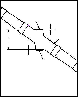
g. Determine bushing (20) thickness for hub (6).
(1) Measure across hub (6) to obtain dimension
A and record dimension A on line 1. Use
caliper.
(2) On each side, measure from each hub (6)
surface to bushing (20) surface to obtain di-
mension 1B and dimension 2B. Record di-
mension 1B and dimension 2B on line 2. Use
caliper.
h. Find center of hub (6):
(1) Divide dimension A by 2 and record on line 3.
(2) Add quotient recorded on line 3 to dimension
1B and record on line 4.
(3) Add quotient recorded on line 3 to dimension
2B and record on line 5.
(4) Identify fork mount (23) as #1 and fork mount
(24) as #2 to match hub markings applied in
step f. Use wax pencil (item 137, App F).
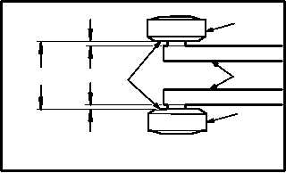
(5) Measure distance between inboard surfaces
of mounts (23) and (24) to obtain dimension
C. Record dimension C on line 6.
(6) Lay a straight edge (25) across inboard sur-
face of elastomeric bearing (26) and measure
distance between straight edge and inboard
surfaces of fork mounts (23) and (24) to ob-
tain dimension 1D and dimension 2D. Record
dimension 1D and dimension 2D on line 7.
GO TO NEXT PAGE
2
1
M04-3245-11
6
TAIL ROTOR HUB MEASUREMENTS (TYPICAL)
1B
A
2B
20
20
25
M04-3245-21
2D
C
1D
TAIL ROTOR FORK MEASUREMENTS (TYPICAL)
1
2
24
23
26