TM 1-1520-238-23
4-157
4.50.
NO. 1 ENGINE INSTALLATION – LOWER CONNECTIONS – continued
4.50.3. Installation
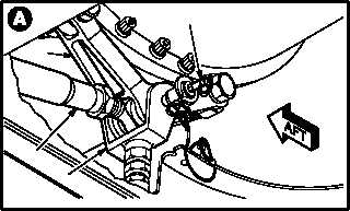
a. Aline aft lower engine mount (1) with lower
link (2) and rod (3).
b. Install quick release pin (4) through mount (1),
link (2), and rod (3).
c. Aline forward lower engine mount (5) with
lower rod (6) and nacelle support (7).
d. Install support pin (8) through mount (5), rod
(6), and support (7).
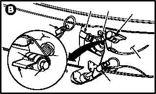
(1) Lock pin (8).
(a) Turn bolt (9) clockwise until lock (10) en-
gages with spring clip (11). Use torque
wrench.
(b) If torque required to lock pin (8) is not 55
to 100 INCH-POUNDS, replace pin.
e. Install two quick release pins (12) through
mount (5) and support (7).
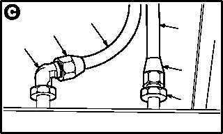
f. Install drain tube (13) on fitting (14).
(1) Hold fitting (14). Install nut (15).
g. Install drain hose (16) on elbow (17).
(1) Hold elbow (17). Install nut (18).
GO TO NEXT PAGE
M04-2995-3
4
3
2
1
M04-2995-4
12
6
5
7
12
8
10
11
9
VIEW
ROTATED
13
16
M04-2995-5
18
17
15
14