TM 1-1520-238-23
4-201
4.63.
NO. 1 OR NO. 2 ENGINE DIRECTIONAL CONTROL SHUTOFF VALVE
REMOVAL/INSTALLATION
4.63.1. Description
This task covers:
Removal. Cleaning. Inspection. Installation.
4.63.2. Initial Setup
Tools:
Aircraft mechanic’s tool kit (item 376, App H)
Light duty laboratory apron (item 27, App H)
Industrial faceshield (item 129, App H)
Chemical protective gloves (item 154, App H)
Materials/Parts:
Packing (2)
Petrolatum (item 138, App F)
Personnel Required:
67R
Attack Helicopter Repairer
67R3F
Attack Helicopter Repairer/Technical
Inspector
References:
TM 1-1520-238-T
TM 55-1500-323-24
Equipment Conditions:
Ref
Condition
1.57
Helicopter safed
2.2
Access doors T250L, T250R, T290L,
T290R, and L325 opened
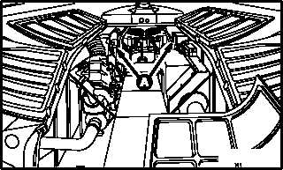
NOTE
This task is typical for No. 1 or No. 2
engine directional control shutoff valves.
4.63.3. Removal
a. Enter pilot station (para 1.56). Observe all
safety precautions.
b. On pilot center circuit breaker panel, open
ENG LVR circuit breaker.
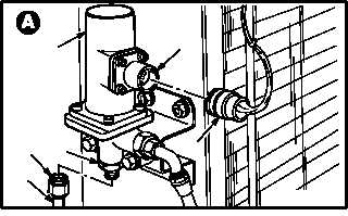
c. Detach connector P62 (1) from No. 1 shutoff
valve (2) receptacle (L11)J1 (3); or detach con-
nector P63 (1) from No. 2 shutoff valve (2)
receptacle (L12)J1 (3).
d. Remove tube (4) from valve (2).
(1) Hold union (5). Remove nut (6).
GO TO NEXT PAGE
M04-1037-1
A
4
2
1
3
6
5
M04-1037-3