TM 1-1520-238-23
Change 1
4-203
4.63.
NO. 1 OR NO. 2 ENGINE DIRECTIONAL CONTROL SHUTOFF VALVE
REMOVAL/INSTALLATION – continued
4.63.6. Installation
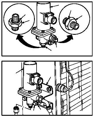
a. Install two new packings (13) on unions (5)
and (8).
(1) Lubricate packings and threads of unions (5)
and (8). Use petrolatum (item 138, App F).
b. Install two unions (5) and (8) on valve (2).
c. Install valve (2) on bracket (10).
(1) Install two bolts (11) through washers (12)
and valve (2) into bracket (10).
d. Install hose (7) on union (8).
(1) Lubricate threads of union (8). Use
petrolatum (item 138, App F).
(2) Hold union (8). Install nut (9).
e. Install tube (4) on union (5).
(1) Lubricate threads of union (5). Use
petrolatum (item 138, App F).
(2) Hold union (5). Install nut (6).
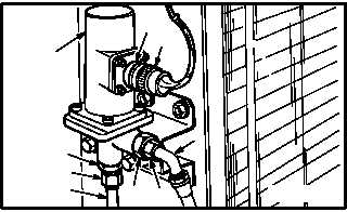
f. Attach connector P62 (1) to No. 1 shutoff
valve (2) receptacle (L11)J1 (3); or attach con-
nector P63 (1) to No. 2 shutoff valve (2) recep-
tacle (L12)J1 (3).
g. Perform pressurized air system leak check
(para 7.115)..
h. Inspect (QA).
i. Secure access doors T250L, T250R, T290L,
T290R, and L325 (para 2.2).
j. Perform power plants maintenance operation-
al
check
(engine
1
or
engine
2)
(TM 1-1520-238-T).
END OF TASK
M04-1037-6
8
13
5
5
8
13
2
10
11
M04-1037-7
12
2
4
2
6
5
M04-1037-8
1
8
9
3
7


