TM 1-1520-238-23
4-462.2
Change 5
4.144A. NO. 1 OR NO. 2 ENGINE LOAD DEMAND SPINDLE GEARBOX MAIN SLEEVE AND RUNOUT
TUBE REMOVAL/INSTALLATION – continued
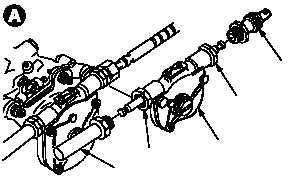
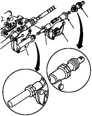
a. Remove main sleeve (1) from load demand
spindle gearbox (2). Hold gearbox (2) at hex-nut
shaped area (3).
b. Remove runout tube (4) from gearbox (2).
Hold gearbox (2) at hex-nut shaped area (5).
4.144A.4. Cleaning
a. Clean removed parts and attaching area (para
1.47).
4.144A.5. Inspection
a. Check attaching areas on gearbox for the fol-
lowing:
(1) Stripped or damaged threads. None allowed.
(2) Cracks. None allowed.
(3) Corrosion (para 1.49).
4.144A.6. Installation
a. Install runout tube (4) on gearbox (2). Hold
gearbox (2) at hex-nut shaped area (5) and tight-
en tube (4).
b. Install main sleeve (1) on gearbox (2). Hold
gearbox (2) at hex-nut shaped area (3) and tight-
en sleeve (1).
c. Inspect (QA).
d. Install cable on No. 1 or No. 2 engine load
demand spindle gearbox (para 4.143 or para
4.144).
e. Perform No. 1 engine or No. 2 engine load
demand spindle rigging check (para 4.184).
f. Perform power plants maintenance opera-
tional check (engine 1 or engine 2)
(TM 1-1520-238-T).
g. Install engine shroud (para 4.51).
h. Secure access door LN1 or RN1 (para 2.2).
END OF TASK
M04-5190-3
2
1
3
4
5
2
1
3
4
5
M04-5190-4


