TM 1-1520-238-23
4-483
4.148.
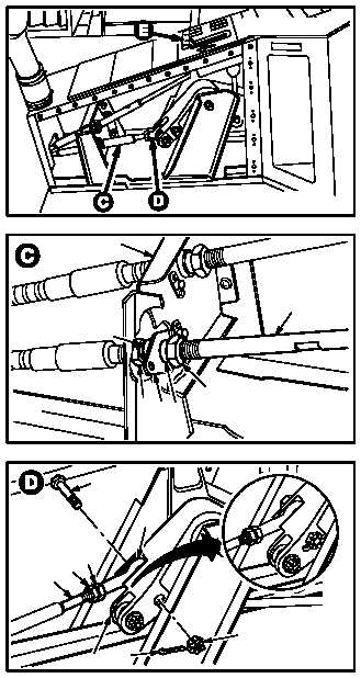
NO. 2 ENGINE POWER AVAILABLE SPINDLE CENTER CABLE INSTALLATION – continued
d. Enter pilot station (para 1.56). Observe all
safety precautions.
e. Install cable (2) on bracket (6).
(1) Center nut (7) on threaded area of cable (2).
(2) Install spacer (8) on cable (2).
(3) Slide cable (2) through bearing (9) on bracket
(6).
(4) Install spacer (10) on cable (2).
(5) Install nut (11) on cable (2). Tighten until
spacer (10) contacts bearing (9).
f. Install rod end (12) on cable (2). Torque nut (13)
to 20 INCH-POUNDS.
(1) Install nut (13) on cable (2) so 0.5 INCH of
cable end is exposed.
(2) Install rod end (12) 0.5 INCH on cable (2) and
aline with bellcrank (14).
(3) Hold rod end (12) at flats (15). Torque nut (13)
to 20 INCH-POUNDS. Use torque wrench.
g. Install rod end (12) on bellcrank (14). Torque
nut (16) 14 to 18 INCH-POUNDS.
(1) Install bolt (17) through bellcrank (14) and rod
end (12).
(2) Install nut (16) on bolt (17).
(3) Hold bolt (17). Torque nut (16) to 14 INCH-
POUNDS. Use torque wrench.
(4) Increase torque to aline cotter pin hole, but do
not exceed 18 INCH-POUNDS.
(5) Install new cotter pin (18).
GO TO NEXT PAGE
PILOT STATION
M04-1186-6
6
2
M04-1186-7
8
7
11
9
10
M04-1186-8
17
12
15
16
18
14
13
2