TM 1-1520-238-23
Change 7
4-601
4.171.
NO. 1 ENGINE POWER AVAILABLE SPINDLE AFT CABLE INSTALLATION – continued
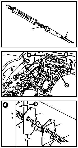
4.171.3. Installation
NOTE
Cables must be installed in a specific di-
rection. Cable end with orange band and
laser etched with ”ENG END” must be
installed on the engine. Cable end with-
out any markings is installed on gearbox.
a. Check cable ribbon (1) friction load.
(1) Place cable (2) on flat surface. Ensure cable
(2) is not bent or twisted.
(2) Slide ribbon (1) 2.5 INCHES in and out of
cable (2). There should be no binding, stiff-
ness, or jamming.
(3) Check friction load of ribbon (1). Load not to
exceed 1.5 POUNDS. Use scale.
(4) If ribbon movement is rough or friction load
exceeds 1.5 POUNDS, replace cable.
b. Install aft cable (2) through seal retainer (3),
firewall plate (4), and louver enclosure (5).
(1) Install coupling nut end of cable (2) aft
through retainer (3).
(2) Pull cable (2) through retainer (3).
(3) Install threaded end of cable (2) forward
through plate (4) and louver enclosure (5).
GO TO NEXT PAGE
2
M04-1200-2
1
M04-1200-3
3
2
5
M04-1200-4
4