TM 1-1520-238-23
Change 8
5-27
5.4.
MAIN ROTOR BLADE INSTALLATION – continued
5.4.3. Installation
NOTE
If blade being installed is a replace-
ment blade, balance weights from re-
moved blade must be installed on
replacement blade.
Blades determined to have inoperable
de-ice shall be re-identified by vibro-
etching an additional letter “A” or -A
after the part number. Upon reidenti-
fication a stencil with 2 inch letters
marking “BLADE DE-ICE INOPER-
ABLE” is required on top and bottom
of the blades.
If TB 1-1520-238-20-62 (Deactivation
of Main Rotor and Tail Rotor Blade De-
ice Capability) is complied with, then
step a. should have been complied
with. If not, perform step a.
A maintenance test flight is not re-
quired when in flight characteristics
are normal and blades have been re-
moved for inspection or shipment,
have not been abused or damaged,
required no adjustments or replace-
ment and are reinstalled in their origi-
nal positions and location.
a. On the pilot aft circuit breaker panel, disable
de-ice system by opening BLADE DE-ICE and
BLADE DE-ICE CONTR circuit breakers. Install
wire tie to prevent reactivation.
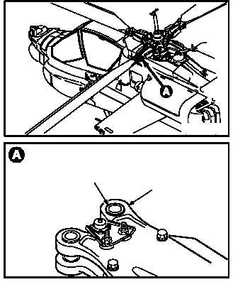
b. Inspect blade (1) for loose blade root fitting
bushings (2). None allowed.
c. Attach crane hook (3) to main rotor sling (4)
lifting ring (5). Use sling set kit.
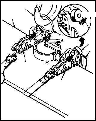
CAUTION
To prevent damage to main rotor blade,
ensure rubber padding is secured to
sling. Padding should be approximately
3/16 inch thick and undamaged. Use care
when installing sling on base.
GO TO NEXT PAGE
M04–206–10
2
1
M04–206–9
M04–206–1
CLOSE
3
1
7
6
OPEN
7
4
5