TM 1-1520-238-23
Change 3
5-29
5.4.
MAIN ROTOR BLADE INSTALLATION – continued
NOTE
If blade was removed for other mainte-
nance, note connector number and
blade serial number recorded during
removal. Install in same position.
Wear clean gloves (item 82, App F)
when handling lead lag link.
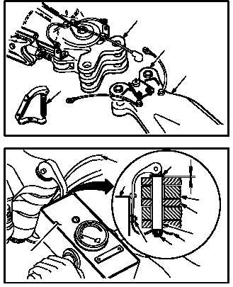
g. Install blade (1).
(1) Use tag lines to position and guide blade (1)
in main rotor blade lead lag link (14).
(2) Aline holes in link (14) with holes in blade root
(15).
(3) Insert main rotor blade pin (16) through link
(14) and root (15).
(4) Move pin (16) up or down to maintain a gap of
0.002 to 0.060 INCH between link (14) and
bottom of pin washer (17).
NOTE
When measuring or adjusting spring clip
tension, blade must be supported so
there will be a minimal load on the pin.
h. Latch clip (18) over nut (19) at bottom of pin
(16).
(1) Aline spring tester (20) with clip (18) and low-
er rivet (21). Use spring tester.
(2) Push spring tester (20) against rivet (21) until
clip (18) latches over nut (19).
NOTE
If 50 to 60 POUNDS closing force is not
indicated, adjust nut to required tension
and repeat step h.
(3) Check for gap of 0.002 to 0.060 INCH be-
tween link (14) and pin washer (17) after ad-
justing and closing clip (18). Repeat step h.
GO TO NEXT PAGE
16
14
15
1
M04-206-8
M04-206-3
15
14
16
18
19
20
21
1
20
17