TM 1-1520-238-23
5-44.2
Change 6
5.7A.
MAIN ROTOR BLADE SPAR TO SPAR DEBOND REPAIR (AVIM) – continued
CAUTION
Spanwise sanding applies to the metallic
area only. The glass skinned area should
be sanded chordwise.
To prevent contamination of bonding pro-
cess, use only filtered pressurized air. Fil-
ter must be capable of removing oil and
debris from air.
5.7A.3. Inspection
a. Clean main rotor blade surface (para 1.47).
NOTE
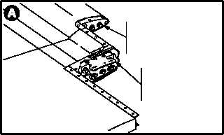
Ensure the locations for the main rotor
blade outboard forward and aft weight
support fittings are not misinterpreted as
debonded area of blade.
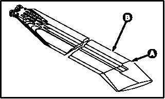
b. Check main rotor blade (1) for debonded
areas.
(1) Tap edge of a coin held between thumb and
forefinger on main blade (1) spar to spar joint
(2). A bonded spot will have a sharp ring. A
debonded spot will have a dull sound.
(2) Visually inspect blade for cracks or raised
seams in areas of spars.
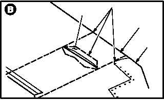
c. Mark area of debonded spar (2) to be repaired.
Use pencil (item 136B, App F).
(1) Mark the outline of the debonded area of
blade.
(2) Place reference marks at the leading and
trailing edge of the blade depicting the ends
of debonded area.
NOTE
For spar debonds located outboard of
F.S. 250.0, remove the main rotor blade
leading edge tip fairing prior to repair.
d. If required remove leading edge tip fairing (3)
(para 5.13).
GO TO NEXT PAGE
M04 5206 1
M04 5206 2
FORWARD
WEIGHT
SUPPORT
FITTING
AFT
WEIGHT
SUPPORT
FITTING
REF MARKS
2
1
3
M04 5206 3