TM 1-1520-238-23
Change 6
5-44.3
5.7A.
MAIN ROTOR BLADE SPAR TO SPAR DEBOND REPAIR (AVIM) – continued
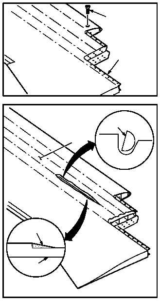
5.7A.4. Repair
NOTE
If spar debond extends underneath spar
No. 1 screw (if installed), remove screw
prior to repair.
a. If required, remove spar No. 1 tip screws (4)
from blade (1).
NOTE
If available, use vacuum while sanding.
b. Sand spanwise to remove paint from de-
bonded spar (2) to expose filler and adhesive.
(1) Sand 0.75 to 1.0 INCHES wide band cen-
tered over spar to spar joint and sand approx-
imately 2.0 INCHES past length of debond at
both ends. Use wheel (item 219A, App F).
(2) Remove filler and adhesive from spar joint.
Use wheel (item 219A, App F).
(3) Using the 1/2 round side of round file, remove
any remaining filler and adhesive. Use 1/2
round file from file set.
NOTE
Pressurized air used shall not exceed 30
PSI, ensure debris is not blown into repair
area.
(4) Remove loose material or debris from repair
area. Use pressurized air and/or vacuum
cleaner.
GO TO NEXT PAGE
M04 5206 4
1
4
M04 5206 5
2
FILLER/ADHESIVE
1
FILE