TM 1-1520-238-23
5-150
Change 7
5.32.
MAIN ROTOR LEAD LAG LINK BEARING RETAINER AND ROTOR HUB BEARING
REMOVAL/INSTALLATION – continued
5.32.3. Removal
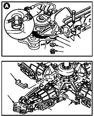
a. Remove two damper rod ends (1) from lead
lag link (2).
(1) Remove sealing compound from attaching
hardware. Use spatula set.
(2) Insert pitch case housing alignment tool. Use
alignment tool (Figure D-475, App D).
(3) Secure alignment tool in place with two quick
release pins (2.1).
(4) Hold bolts (3). Remove nuts (4) and washers
(5). Use ratchet and box wrench.
(5) Discard nuts (4).
(6) Remove bolts (3), angle brackets (6), sleeve
bushings (7), and washers (8).
(7) Swing rod ends (1) free from link (2).
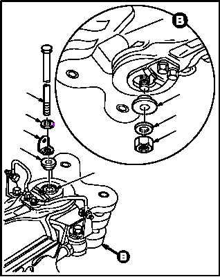
b. Remove center bolt (9) from lead lag link pin
(10).
(1) Hold bolt (9). Remove nut (11), washer (12),
and sleeve bearing (13).
(2) Remove bolt (9), washer (14), bracket (15),
and sleeve bearing (16) from pin (10).
GO TO NEXT PAGE
M04–230–11
2
4
5
1
6
7
3
8
8
M04–230–14
2.1
ALIGNMENT
TOOL
2
STRAP
PACK
M04–230–3
13
12
11
9
14
15
16
10