TM 1-1520-238-23
6-40
Change 1
6.8.
NO. 4 TAIL ROTOR DRIVE SHAFT, DAMPER, AND ANTI-FLAIL SUPPORT
REMOVAL/INSTALLATION – continued
NOTE
Tension washer(s) may be missing due to
damper tension adjustment.
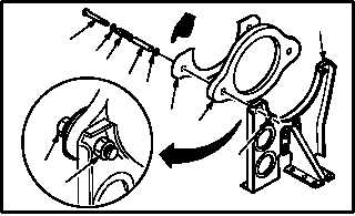
o. Check both sides of support (7) for presence of
screw (14), washer (15), spring (16), spacer
(17), tension washer (18), plate (19), and nut
(21).
p. Check both sides of support (7) and ensure
that at least one screw thread of screw (14)
extends through nut (21).
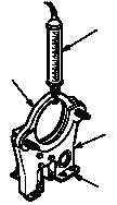
q. Check tension of damper (22).
(1) Position scale (23) in center of damper (22).
Use scale.
(2) Hold base of support (7) and pull on scale
(23) until damper (22) moves. Note reading
on scale (23) dial indicator at instance damp-
er (22) moves.
(3) If scale (23) dial indicator shows that damper
(22) requires less than 9 or more than 11
pounds of tension to move, adjust damper
(22) tension (para 6.8.6).
6.8.6. Adjustment
a. Adjust damper (22) tension. Torque nut (21) to
13 INCH-POUNDS.
(1) Remove nut (21).
NOTE
More than one tension washer may be
installed between spring and plate.
(2) Remove screw (14), washer (15), spring (16),
spacer (17), and tension washer (18) (if
installed) from both sides of plate (19), damper
(22), and support (7).
GO TO NEXT PAGE
M04-441-8A
14
1516
17
19
22
21
18
7
14
21
M04-441-9
23
22
7
BASE
M04-441-10A
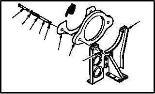
14
15
16
17
19
21
18
7
22