TM 1-1520-238-23
Change 4
6-41
6.8.
NO. 4 TAIL ROTOR DRIVE SHAFT, DAMPER, AND ANTI-FLAIL SUPPORT
REMOVAL/INSTALLATION – continued
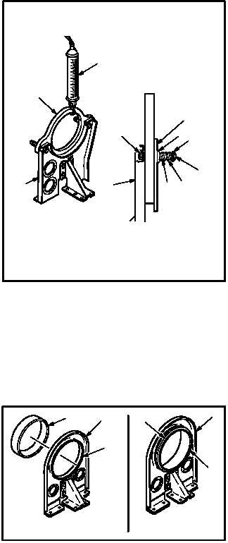
(3) If reading on scale (23) dial indicator was less
than 9 pounds, increase tension of damper by
adding tension washers (18) one at a time on
each side of support (7) until correct tension
reading on scale (23) is obtained.
(4) If reading on scale (23) dial indicator was
more than 11 pounds, decrease tension of
damper by removing tension washers (18)
one at a time on each side of support (7) until
correct tension reading on scale (23) is ob-
tained.
NOTE
Replace one or both springs if minimum
length is less than 0.40 INCH. Do not
stretch spring in order to increase length.
(5) If correct tension reading on scale (23) is not
obtained when only one tension washer (18)
remains on each side of support (7), replace
spring (16).
(6) Install screw (14) through washer (15), spring
(16), spacer (17), and tension washer(s) (18) on
both sides of plate (19), damper (22), and sup-
port (7).
(7) Hand tighten nut (21) on screw (14).
(8) Torque nut (21) to 13 INCH-POUNDS. Use
torque wrench.
6.8.7. Repair
a. Repair support (1) by replacing sleeve (24).
(1) Remove bends in support lip of ring (25).
(2) Remove and discard sleeve (24).
(3) Install new sleeve (24).
(4) Crimp lip of ring (25) between bends to se-
cure sleeve (24).
GO TO NEXT PAGE
22
M04-441-11A
21
1815
14
16
7
7
17
23
19
M04-441-13
24
25
1
1
24
25