TM 1-1520-238-23
7-409
7.109.
UTILITY HYDRAULIC TUBING BULKHEAD SUPPORT BRACKET
REMOVAL/INSTALLATION – continued
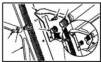
7.109.6. Installation
a. Install bracket (11) on bulkhead (19).
(1) Aline bracket (11) with bulkhead (19) and
unions (2) and (15).
(2) Install two screws (20), washers (21), and
nuts (22).
b. Install hose (14) on union (15).
(1) Hold union (15). Install washer (18) and nut
(17).
(2) Lubricate threads of union (15). Use clean
hydraulic fluid (item 92, App F).
(3) Install nut (16) fingertight on union (15).
(4) Aline hose (14) to 135 degrees.
(5) Hold union (15). Tighten nut (16).
c. Install tee (9) on bracket (11).
(1) Insert tee (9) through bracket (11).
(2) Hold tee (9). Install washer (13) and nut (12).
d. Install tube (8) on tee (9).
(1) Lubricate threads of tee (9). Use clean
hydraulic fluid (item 92, App F).
(2) Hold tee (9). Install nut (10).
e. Attach connector P1072 (6) to rotor brake
pressure switch (S88)J1 (7).
GO TO NEXT PAGE
M04-3643-6
22
21
20
2
15
19
11
17
16
18
15
14
6
7
9
13
12
10
8
14
16
LOOKING AFT
M04-3643-7
11
0º
180º
135º