TM 1-1520-238-23
6-84
Change 4
6.14.
NO. 6 TAIL ROTOR DRIVE SHAFT REMOVAL/INSTALLATION – continued
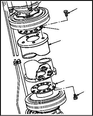
6.14.6. Installation
CAUTION
When installing No. 6 tail rotor drive shaft,
ensure that bolts are installed through
0.250 INCH bolt holes on the intermedi-
ate gearbox output coupling flange and
on the tail rotor gearbox input coupling
flange. Do not install bolts through any of
0.500 INCH lightening holes. Installation
of bolts through lightening holes will re-
sult in failure of drive shaft and/or cou-
plings.
a. Install drive shaft (1). Torque bolts (2) and (4) to
125 INCH-POUNDS.
(1) Push down on flange (5).
(2) Position shaft (1) between flanges (3) and (5).
(3) Aline bolt holes in flanges (3) and (5) with bolt
holes in shaft (1).
(4) Install five bolts (4) through flange (5) and
shaft (1).
(5) Install five bolts (2) through flange (3) and
shaft (1).
(6) Torque bolts (2) and (4) to 125 INCH-
POUNDS. Use torque wrench and torque
wrench adapter.
(7) Apply corrosion preventive compound to
bolts (2) and (4). Use corrosion preventive
compound (item 62A, App F).
b. Inspect (QA).
c. Install access fairings L510, R510, L530, and
L540 (para 2.2).
d. Perform drive system vibration mainte-
nance operational check (TM 1-1520-238-T).
END OF TASK
M04-0453-4
2
3
1
5
4