TM 1-1520-238-23
6-87
6.15.
TAIL ROTOR GEARBOX INPUT COUPLING REMOVAL/INSTALLATION – continued
6.15.5. Inspection
NOTE
Unless otherwise specified, the following
inspection procedures apply to the tail ro-
tor gearbox input coupling, anti-flail bearing
sleeves, tail rotor gearbox input flange,
and upper end of No. 6 tail rotor drive
shaft.
a. Check for cracks. None allowed.
b. Check for corrosion (para 1.49).
c. Check for nicks and scratches (para 6.1).
d. Check upper end of No. 6 tail rotor drive shaft
for dents (para 6.1).
e. Check tail rotor gearbox input coupling and tail
rotor gearbox input flange for elongated bolt
holes (para 6.1).
f. Check tail rotor gearbox input coupling and
upper end of No. 6 tail rotor drive shaft for
loose or damaged nutplates (para 6.1).
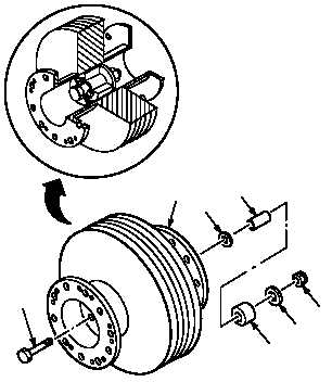
6.15.6. Installation
a. Install sleeves (9) and (8) in coupling (1).
Torque nut (10) to 35 INCH-POUNDS.
(1) Install bolt (13) in coupling (1).
(2) Install washer (12), sleeves (9) and (8), and
washer (11) on bolt (13).
(3) Hand tighten nut (10) on bolt (13).
(4) Torque nut (10) to 35 INCH-POUNDS. Use
torque wrench.
GO TO NEXT PAGE
13
1
12
9
11
10
8
M04-0455-5