TM 1-1520-238-23
8-17
8.5.
ENGINE/ROTOR RPM INDICATOR FRONT PANEL REMOVAL/INSTALLATION (AVIM)
8.5.1. Description
This task covers:
Removal. Cleaning. Inspection. Installation.
8.5.2. Initial Setup
Tools:
Electrical tool kit (item 378, App H)
Light duty laboratory apron (item 27, App H)
3/16-inch flat tip screwdriver bit (item 31, App H)
Industrial faceshield (item 129, App H)
Chemical protective gloves (item 154, App H)
Large wrist grounding strap (item 346, App H)
1 - 100 inch-ounce 1/4-inch hexagon drive click type
torque wrench (item 437, App H)
Materials/Parts:
Cloth (item 52, App F)
Lubricant (item 115, App F)
Personnel Required:
68X
Armament/Electrical System Repairer
68X3F
Armament/Electrical System Repairer/
Technical Inspector
CAUTION
Static electrical discharge can damage
semiconductors in circuit card. To pre-
vent damage, repairer must wear
grounding strap when panel is off, and
when handling circuit card.
8.5.3. Removal
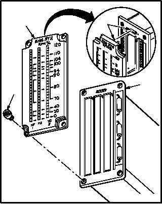
a. Remove front panel (1) from indicator case
(2). Wear grounding strap.
(1) Remove four bushings (3).
(2) Carefully pull panel (1) away from case (2)
until connector (4) detaches.
8.5.4. Cleaning
a. Wipe panel and indicator case. Use cloth
(item 52, App F).
GO TO NEXT PAGE
4
1
2
3
M04-2677-3


