TM 1-1520-238-23
8-12
8.2.
TYPICAL ENGINE INSTRUMENT INDICATOR DISASSEMBLY/ASSEMBLY (AVIM) – continued
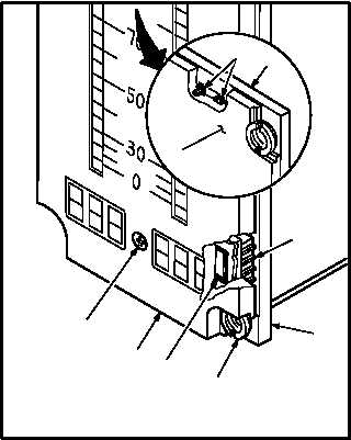
CAUTION
Do not exceed 24 INCH-OUNCES torque
on bushings.
NOTE
Step h is typical for fuel quantity, NG, TGT,
and torque indicators.
h. Install panel (1). Torque four bushings (2) to 24
INCH-OUNCES. Torque screw (3) to 37 INCH-
OUNCES.
(1) Lubricate four bushings (2). Use lubricant
(item 115, App F).
(2) Ensure filter (22) is seated in recess of driver
(23).
(3) Aline connector (4) and position panel (1) on
case (9). Press to engage connector (4).
(4) Install four bushings (2). Torque four bush-
ings to 24 INCH-OUNCES. Use torque
wrench and screwdriver bit.
(5) Install screw (3). Torque screw to 37 INCH-
OUNCES. Use torque wrench and
screwdriver bit.
i. Inspect (QA).
END OF TASK
9
4
1
M04-3084-14
1
3
9
2
22
23