TM 1-1520-238-23
8-54
8.20.
SIGNAL DATA CONVERTER POWER SUPPLY REPLACEMENT (AVIM) – continued
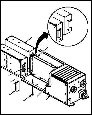
c. Remove power supply (7) from chassis (3).
Use grounding strap and shunt bar (8).
(1) Remove six screws (9) from bottom of chas-
sis (3).
(2) Grasp power supply (7) and pull toward front
of frame (10) to detach connector P1 (11)
from receptacle (A14)J1/(A15)J1 (12).
(3) Remove power supply (7) from chassis (3).
Install bar (8) on connector (11).
(4) Store removed power supply (7), with bar (8)
installed, in a storage bag. Use shipping and
storage bag (item 182, App F).
8.20.4. Cleaning
a. Clean removed and attaching parts. Use cloth
(item 52, App F).
8.20.5. Inspection
a. Check chassis and covers for cracks, nicks,
and dents. None allowed.
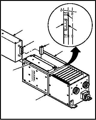
8.20.6. Installation
a. Install power supply (7) in chassis (3). Use
grounding strap. Torque six screws (9) to 80
INCH-OUNCES.
(1) Remove power supply (7) from plastic bag.
Remove bar (8).
(2) Position power supply (7) inside chassis (3).
(3) Slide power supply (7) toward front of frame
(10) to attach connector P1 (11) to receptacle
(A14)J1/(A15)J1 (12) and aline screw holes.
GO TO NEXT PAGE
M04-3410-2
3
12
9
10
11
8
7
3
7
10
8
11
11
7
12
7
M04-3410-3
ALINEMENT
PINS