TM 1-1520-238-23
Change 4 8-73
8.27.
FUEL SIGNAL CONDITIONER REMOVAL/INSTALLATION – continued
8.27.4. Cleaning
a. Wipe shelf and conditioner with a clean rag.
8.27.5. Inspection
a. Check conditioner and shelf for dents, nicks,
and cracks. None allowed.
b. Check shelf screw holes for stripped or dam-
aged threads. Acceptable thread damage can-
not exceed 50 percent of one thread.
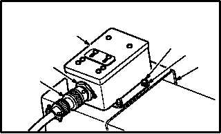
8.27.6. Installation
a. Install conditioner (1) on shelf (2).
(1) Aline conditioner base with shelf (2) screw
holes. Receptacle (4) must face outboard.
(2) Install four screws (5) and washers (6).
(3) Attach connector P937 (3) to receptacle
(A308)J1 (4).
b. Inspect (QA).
c. Install access cover L40 (para 2.2).
d. Perform fuel quantity system-capacitance
and indicating test (TM 1-1520-238-T).
e. Perform engine instruments maintenance op-
erational check (TM 1-1520-238-T).
END OF TASK
M04-163-5
1
2
4
3
5
6