TM 1-1520-238-T-4
3–7
3–2.
LOCATION AND DESCRIPTION OF MAJOR COMPONENTS (cont)
3–2
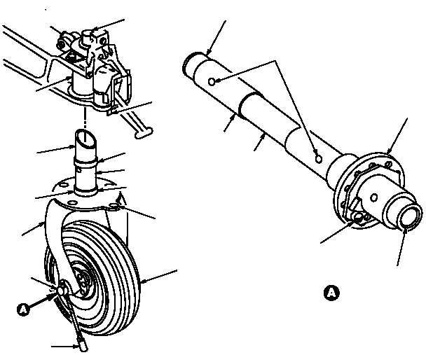
(4) Wheel Centering Mechanism.
The wheel centering mechanism is mounted into the trailing arm
socket and fork assembly and consists of a center pivot shaft, a lower cam, and an upper cam. The center pivot
shaft of the fork contains two internal springs, a spring guide, and a lower cam. The lower cam is retained in the
fork assembly by a headless pin through a slot in the cam which allows it to move up and down on the fork liner
during activation. The upper cam is retained in the upper cam housing assembly by a headless pin. The stationary
cam mates with the lower cam. When the fork rotates it forces the lower cam down. Internal spring tension at the
the lower cam causes the the fork assembly to center when weight is removed from the TLG.
(5) Wheel and Tire Assembly.
The wheel and tire assembly mounts on the fork axle and consists of a
wheel, a tire and a tube. The tire is a 14–ply tubeless rib tread design with an inner tube installed to provide added
impact protection. The TLG tire is inflated to 95 5 psi using dry nitrogen. Tire burst pressure is 340 psi. The
wheel is a split–rim type with the halves bolted together. Left and right taper roller anti–friction, internally mounted
bearings are used to ride the axle. Two spacers are installed internally on the axle, one non–adjustable, the other
adjustable. Spacers center the wheel on the axle and a locknut provides bearing adjustment and wheel free play.
M58-099A
LOCK NUT
AXLE
ADJUSTABLE SPACER
BUSHING (2)
WHEEL AND TIRE
ASSEMBLY
FORK
ASSEMBLY
LOWER CAM
UPPER CENTERING
CAM HOUSING
LOCK
ACTUATOR PIN
TRAILING ARM
SOCKET
DUST SEAL
AXLE ASSEMBLY
STATIC
GROUND CABLE
MOUNT SECURING
HOLES
WEAR PLATE
LOCKING PIN HOLE
TOW BAR
ATTACHING
POINT
UPPER CAM PIN
CENTER PIVOT SHAFT
LOWER CAM PIN
TAPERED AXLE
SPACER
NON-ADJUSTABLE SPACER
Figure 3–7.
Fork and Axle Assembly, Wheel Centering Mechanism, and Wheel
and Tire Assembly