TM 1-1520-238-T-5
7–24
Change 1
7–7.
SYSTEM DESCRIPTION (cont)
7–7
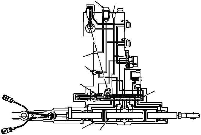
(e) The longitudinal, collective, lateral and directional servocylinders (fig. 7–9) are of tandem design
which utilize primary and utility hydraulic system pressure. The servocylinder has two modes of operation, normal
and BUCS (refer to TM 1-1520-238-T-7 for BUCS mode of operation). During normal (mechanical input) mode of
operation, pressurized fluid from the primary hydraulic manifold enters the servocylinder through port P1. Fluid is
filtered by a 25 micron filter and routed through a one–way check valve to the stability augmentation actuator. The
check valve prevents pressurized fluid from being forced back through the pressure port. The manual servo valve
and stability augmentation actuator control both the primary and utility system fluids in the servocylinder. The
position of the manual servo valve and stability augmentation actuator determine if fluid pressure is equalized or
routed to the power piston and primary barrel. When one side of the piston is pressurized, the other side is routed
through return port R1 to the primary hydraulic reservoir.
M68-107
RETURN PRI R1
ACTUATOR
STABILITY AUGMENTATION
POWER
PISTON
SERVO VALVE
MANUAL
CHECK VALVE
PRIMARY
PI PRESSURE
FILTER
PRIMARY
BARREL
Figure 7–9.
Servocylinder Functional Diagram