TM 1-1520-238-T-5
8–15
8–7.
SYSTEM DESCRIPTION (cont)
8–7
(3) Miscellaneous instruments display hydraulic pressure, fuel quantity, outside temperature, and time.
Each instrument operates independently with some readings being duplicated when identical instruments are
located in both crew stations.
b. Engine Instruments.
(1) Purpose.
Engine instruments measure and display helicopter engine and rotor performance. Pilot’s
indicator edge–lighting is controlled by the pilot EXT LT/INTR LT panel. CPG’s indicator edge–lighting is
controlled by CPG INTR LT panel. The pilot dim/test panel provides display lamp test, display lamp dim automatic
control, and digital blanking. The CPG SDD provides the display lamp test for the CPG’s indicator.
(2) System of Operation.
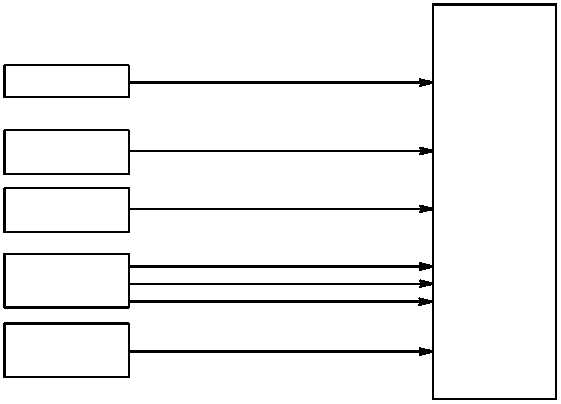
(a) The pilot TGT indicator (fig. 8–6) receives operating and lamp supply voltages from the SDC. Engine
turbine 1 and 2 temperature sensors supply temperature data to the indicators.
TGT INDICATOR
M68-116
PILOT EXT LT /
INTR LT PANEL
PILOT DIM /
TEST PANEL
TURBINE 1
TEMPERATURE SENSOR
SDC
OPERATING / LAMP SUPPLY VOLTAGES
TURBINE 1 TEMPERATURE DATA
DISPLAY LAMP TEST
PANEL EDGE - LIGHTING
TURBINE 2
TEMPERATURE SENSOR
TURBINE 2 TEMPERATURE DATA
DISPLAY LAMP DIM / BRIGHT AUTOMATIC CONTROL
DIGITAL BLANKING
Figure 8–6.
Pilot TGT Indicator Functional Block Diagram