TM 1-1520-238-T-5
8–16
8–7.
SYSTEM DESCRIPTION (cont)
8–7
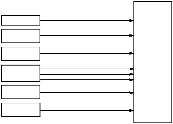
(b) The engine TORQUE indicators (fig. 8–7) receive operating and lamp supply voltages from the SDC.
Engine 1 and 2 torque sensors supply torque data to the indicators.
(c) The pilot ENG–OIL indicator (fig. 8–8) receives operating and lamp supply voltages from the SDC.
Engine 1 and 2 oil pressure sensors supply oil pressure data.
(d) The ENG–RTR RPM% indicators (fig. 8–9) receive operating and lamp supply voltages from the
SDC. Engine 1 and 2 rpm sensors supply engine rpm (NP) data. The main rotor rpm sensor supplies rotor rpm
(NR) data.
(e) The pilot NG RPM% indicator (fig. 8–10) receives operating and lamp supply voltages from the SDC.
Engine 1 and 2 gas generator rpm sensors supply required data.
TORQUE INDICATOR
M68-114
CPG INTR LT OR PILOT EXT
LT / INTR LT PANELS
PILOT DIM /
TEST PANEL
ENGINE 1
TORQUE SENSOR
SDC
OPERATING / LAMP SUPPLY VOLTAGES
TORQUE DATA
DISPLAY LAMP TEST (PILOT)
PANEL EDGE - LIGHTING
ENGINE 2
TORQUE SENSOR
TORQUE DATA
DISPLAY LAMP DIM / BRIGHT AUTOMATIC CONTROL
CPG SDD TEST
SWITCH
DISPLAY LAMP TEST (CPG)
DIGITAL BLANKING (PILOT)
Figure 8–7.
TORQUE Indicator Functional Block Diagram