TM 1-1520-238-T-5
8–22
8–7.
SYSTEM DESCRIPTION (cont)
8–7
c. Flight Instruments.
(1) Purpose.
Flight instruments measure and display helicopter performance and provide visual
displays of attitude and flight conditions. Pilot’s indicator edge–lighting is controlled by the pilot EXT LT/INTR LT
panel. CPG’s indicator edge–lighting is controlled by CPG INTR LT panel.
(2) System of Operation.
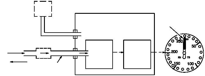
(a) The airspeed indicator (fig. 8–14) is connected to the static port for air pressure reference. As the
helicopter moves forward, the Pitot tube provides ram air into an airtight diaphragm. The expanding diaphragm
triggers the mechanical multiplier. The mechanical multiplier drives the instrument pointer to display airspeed on
the calibrated indicator dial.
STATIC
PORT
AIRTIGHT
DIAPHRAGM
MECHANICAL
MULTIPLIER
AIR
FLOW
PITOT
TUBE
AIR PRESSURE
DIRECTION OF
HELICOPTER
FLIGHT
AIRSPEED INDICATOR
AIRTIGHT CASE
S
P
M68-124
POINTER
Figure 8–14.
Airspeed Indicator Functional Block Diagram
(b) The VSI (fig. 8–15) is connected to the static port for air pressure reference. The VSI has a capillary
tube for air pressure. Air pressure inside and outside is equal when the helicopter remains at the same altitude.
Pressure changes are sensed by the airtight diaphragm when the helicopter moves up or down. The airtight
diaphragm moves the mechanical multiplier. The mechanical multiplier proportionally moves the indicator dial
clockwise for upward movement and counter–clockwise for downward movement.