TM 1-1520-238-T-5
8–23
8–7.
SYSTEM DESCRIPTION (cont)
8–7
STATIC
PORT
AIRTIGHT
DIAPHRAGM
MECHANICAL
MULTIPLIER
M68-125
SEALED CASE
OUTSIDE
AIR
PRESSURE
CAPILLARY
TUBE
ZERO ADJUST
POINTER
VSI
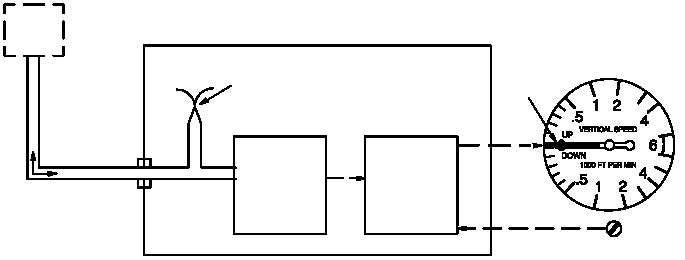
Figure 8–15.
VSI Functional Block Diagram
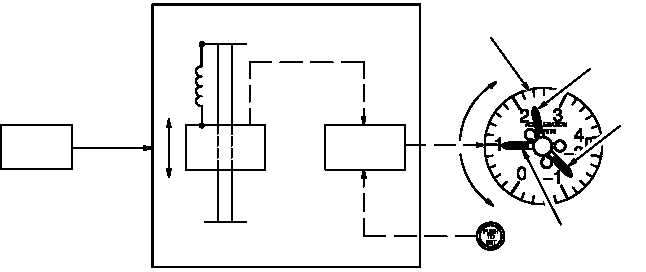
(c) The pilot accelerometer (fig. 8–16) indicates positive and negative changes in gravity. The
accelerometer has a weight attached internally to a spring for +1g reference. When the helicopter is moving up,
force is applied to the weight and moves it down the shaft. The mechanical linkage moves the continuous pointer
and maximum pointer in a clockwise direction. When the helicopter is moving down, force is applied to the weight
and moves it up the shaft. The mechanical linkage moves the continuous pointer and maximum pointer in a
counter–clockwise direction. The maximum and minimum pointers are connected to ratchets. These pointers
follow the continuous pointer, but stop and remain at the highest reading reached until reset to +1g by the PUSH
TO SET control.
MAXIMUM
G - READING
POINTER
MINIMUM
G - READING
POINTER
CONTINUOUS
POINTER
DIAL
M68-126
+G
-G
METER
MOVEMENT
WEIGHT
BLOCK
-G
SHAFT
SPRING
MECHANICAL
LINKAGE
ACCELEROMETER
PILOT EXT
LT / INTR
LT
PANEL
0 - 5 VDC
EDGE -
LIGHTING
PUSH TO
SET CONTROL
+G
Figure 8–16.
Pilot Accelerometer Functional Block Diagram