TM 1-1520-238-T-6
9–81
9–7.
SYSTEM DESCRIPTION (cont)
9–7
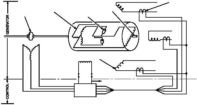
(e) The ac generators (fig. 9–73) convert mechanical energy to electrical energy. A generator consists
of a permanent magnetic generator (PMG), exciter and main generator. The PMG provides 3-phase, 22 VAC
self-excitation for exciter field current when the accessory gearbox in the main transmission is turning.
(f) The exciter field current is controlled by a voltage regulator circuit in the GCU. The current source is
the rectified PMG voltage. The stationary exciter control field current induces ac voltage in the rotating exciter
field. The rotating exciter field voltage is rectified by the diode assembly and applied to the rotating main field.
(g) The main generator rotating field induces 115 VAC in each of the main field stationary windings
(three). The output is 115 VAC, 3-phase, 400 Hz. Current sensing transformers provide phase current inputs to
the GCU for overcurrent protection.
CURRENT
SENSING
XFMRS
T1
T4
MAIN ROTATING
FIELD
DIODE ASSY
ROTATING
EXCITER
FIELD
PERMANENT
MAGNET
T2
T4
STATIONARY MAIN
GENERATOR AC WINDINGS
STATIONARY
PMG WINDING
STATIONARY
EXCITER CONTROL
FIELD
CONTROLLED EXCITER
FIELD CURRENT FROM GCU
GCU
LOW VOLTAGE
AC OUTPUT
TO GCU
TO RH FAB MRTU
3Ø
CURRENT
SENSING
M69-349
T4
T3
Figure 9–73.
AC Generator Functional Block Diagram
(h) The GCU (fig. 9–74) provides circuit protection and controls the operation of the generators. In
normal operation, the GCU energizes the generator control relay (GCR) and contactor control relay (CCR).
(i) The PMG input voltage is checked for underfrequency (on ground only), rectified, and sent to the ac
and dc voltage regulators. The squat switch provides an underfrequency ground only protection. If
underfrequency occurs, the generator is disconnected from the bus by the GCR.
(j) The generator output voltage is monitored for overvoltage/undervoltage and is regulated by the ac
voltage regulator. If output voltage varies, the ac regulator provides feedback to the generator exciter field to offset
the voltage variation. If the voltage remains out-of-limits, the switching unit deenergizes the CCR, disconnecting
the generator from the bus.


