TM 1-1520-238-T-6
9–172
9–23.
DC ELECTRICAL POWER GENERATION – MAINTENANCE OPERATIONAL CHECK (cont)
NOTE
Refer to pilot station (fig. 9–103) for configuration and component
locations.
If referenced out of one paragraph or volume into another for additional
troubleshooting, upon completion of the task, return to the maintenance
operational check for the original paragraph or volume.
1. Perform the maintenance operational check as follows:
Task
Result
a. Connect battery (TM 1-1520-238-23).
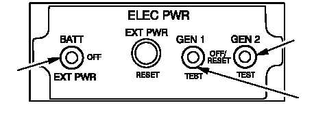
b. On pilot ELEC PWR panel (fig. 9–104),
place BATT/EXT PWR switch to BATT.
M69-064
BATT / EXT PWR
SWITCH
GEN 1 SWITCH
GEN 2 SWITCH
Figure 9–104.
Pilot ELEC PWR Panel
c. On pilot master caution/warning panel (fig.
9–105), press and hold the PRESS TO
TEST indicator. Verify that all indicators are
lighted.
If caution/warning indicators are lighted, go to
paragraph 9–41 to troubleshoot battery.
If RECT 1 indicator does not light, replace lamp.
(TM 1-1520-238-23). If lamp still does not light, go to
paragraph 9–25.
If RECT 2 indicator does not light, replace lamp
(TM 1-1520-238-23). If lamp still does not light, go to
paragraph 9–26.
PRESS TO TEST
INDICATOR
M69-065
Figure 9–105.
Pilot Master Caution/Warning Panel


