TM 1-1520-238-T-6
9–175
9–23.
DC ELECTRICAL POWER GENERATION – MAINTENANCE OPERATIONAL CHECK (cont)
Task
Result
k. Check for 28 VDC at (A402):
J29-1, J29-2, J29-3 and J32-G
(pilot dc emergency bus).
If voltage is not present on one pin and is present on
the others, go to paragraph 9–36.
l. On pilot ELEC PWR panel (fig. 9–104), set
BATT/EXT PWR switch to OFF.
m. Reconnect P4, P5, and P461 to their mating
connectors. Install cover on electrical power
distribution box.
n. Perform AUXILIARY POWER UNIT –
POWER UP (TM 1-1520-238-T-8).
o. On pilot ELEC PWR panel, set and hold
GEN 1 switch to TEST. On pilot
caution/warning panel (fig. 9–108), check
that GEN 1 indicator is not lighted.
If GEN 1 indicator is lighted, go to paragraph 9–12 to
troubleshoot ac electrical power generation.
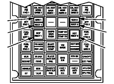
M69-067
GEN 2
INDICATOR
RECT 2
INDICATOR
HOT RECT 2
INDICATOR
GEN 1
INDICATOR
RECT 1
INDICATOR
HOT RECT 1
INDICATOR
Figure 9–108.
Pilot Caution/Warning Panel
p. Release GEN 1 switch. Set and hold GEN 2
switch to TEST. On pilot caution/warning
panel check that GEN 2 indicator is not
lighted.
If GEN 2 indicator is lighted, go to paragraph 9–12 to
troubleshoot ac electrical power generation.
q. On pilot ELEC PWR panel (fig. 9–104),
release GEN 2 switch. Set GEN 1 switch to
GEN 1. On pilot caution/warning panel
check that RECT 1 and HOT RECT 1
indicators are not lighted.
If RECT 1 indicator is lighted, go to paragraph 9–37.
If HOT RECT 1 indicator is lighted, go to
paragraph 9–38.