TM 1-1520-238-T-7
11–56
11–7.
SYSTEM DESCRIPTION (cont)
11–7
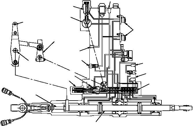
(d) When BUCS is engaged, the SAS and BUCS solenoid valves are energized open. Pressurized
hydraulic fluid is applied through the open SAS and BUCS valves to the BUCS plunger. The BUCS plunger is
forced out to engage the output arm, locking out manual control inputs. With manual control inputs locked out, the
EHV becomes the only source of control for the helicopter. When a cyclic stick, collective stick or directional pedal
is moved, a signal is developed by the appropriate LVDT and applied to the DASEC. A command signal from the
DASEC is applied to the EHV. The EHV flapper valve is displaced from the neutral position, causing the SAS
cylinder to move. Movement of the SAS cylinder opens hydraulic ports to the power piston. The power piston
extends or retracts as directed by the EHV flapper valve. As the power piston moves, the power piston severs the
BUCS shear pin, separating the servocylinder from the mechanical flight control linkage.
(e) The dual position LVDT provides a feedback signal of opposite polarity to the DASEC where it is
summed with the command signal. The resulting summation signal nulls out the command signal. When the
command signal is nulled out, the EHV flapper valve returns to the neutral position. Equalized pressure on the
SAS cylinder causes cylinder movement to stop and remain in position until another command signal input is
received.
PILOT INPUT
LEVER
DUAL
POSITION
LVDT
STABILITY AUGMENTATION
ACTUATOR
SAS
SOLENOID VALVES
BUCS
RETURN PRI
RETURN UTILITY
PRESSURE
UTILITY
TWO-STAGE
ELECTRO-HYDRAULIC
SERVO VALVE (EHV)
POWER PISTON
SAS LVDT
MANUAL
SERVO VALVE
CHECK VALVE
PRESSURE
PRIMARY
MANUAL SERVO
VALVE INPUT ARM
OUTPUT
ARM
BUCS
PLUNGER
BUCS
SHEAR
PIN
M70-266A
Figure 11–28.
Hydraulic Servocylinder DASE and BUCS Interface Diagram