TM 1-1520-238-T-7
11–53
11–7.
SYSTEM DESCRIPTION (cont)
11–7
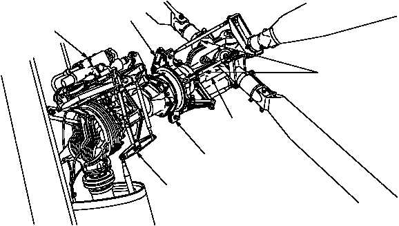
(f) The directional servocylinder (fig. 11–26) is hydraulically operated and connected to the directional
bellcrank. The directional servocylinder hydraulically assists the mechanical control linkage by changing pitch on
the tail rotor blades. The directional bellcrank provides a push-pull action to the nonrotating swashplate. The drive
links transmit nonrotating swashplate motion to the rotating swashplate. The rotating swashplate transmits
movement to the pitch change link assemblies, changing pitch angle on the tail rotor blades. The fork assembly
provides drive link attachment points and provides mounting for the tail hubs.
M70-264A
PITCH CHANGE
LINKS
FORK
ASSEMBLY
SWASHPLATE
ASSEMBLY
DIRECTIONAL
MECHANICAL
CONTROL
LINKAGE
DRIVE LINKS
DIRECTIONAL
SERVOCYLINDER
Figure 11–26.
Tail Rotor Directional Control System Interface Diagram
g. DASE.
(1) Purpose.
The purpose of the DASE system is to receive and transmit flight reference signals for
control and stability of the helicopter.
(2) System Operation.
(a) The DASEC (fig. 11–27) is supplied 28 VDC power through the ASE DC circuit breaker (CB28). The
BUCS and tracer wire severance monitoring is supplied 28 VDC operating power through the ASE BUCS circuit
breaker (CB77). Two excitation transformers are supplied 115 VAC through the ASE AC circuit breaker (CB18).
The excitation transformers step down 115 VAC to 26 VAC for DASEC and LVDT operations. (ACB) Transformers
are housed in a LRU with four filters. The filters are used for EMI hardening.