TM 1-1520-238-T-7
11–130
Change 7
11–19.
COLLECTIVE FLIGHT CONTROLS – RIGGING OPERATIONAL CHECK (cont)
11–19
Task
Result
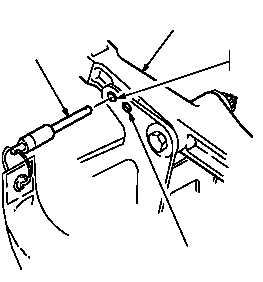
d. In lateral servocylinder bellcrank
(fig. 11–64.1) install -5 rig pin and cyclic
stick warning flag.
If rig pin cannot be installed, perform lower flight
control rigging between pilot and CPG cyclic sticks
and lateral servocylinder bellcrank
(TM 1-1520-238-23).
e. In longitudinal servocylinder bellcrank
(fig. 11–63), install -5 rig pin at the level
swashplate rig pin hole. Install pilot and
CPG cyclic stick warning covers.
f. On collective servocylinder (fig. 11–64),
verify that lower lever is aligned with upper
edge of boss on servocylinder body.
If lower lever is not aligned with upper edge of boss,
rig collective flight controls between pilot collective
stick and collective servocylinder
(TM 1-1520-238-23).
g. On right side of mast base (fig. 11–65),
install main rotor rigging plate
(TM 1-1520-238-23).
h. In head of mixer support bolt (fig. 11–65),
install alignment tool. Place main rotor
rigging fixture on main rotor rigging plate
next to alignment tool. Loosen thumb screw
on rigging fixture. Align BASIC DIM pointer
on rigging fixture with center point on
alignment tool. Tighten thumbscrew.
NOTE
The longitudinal bellcrank forward bolt head is located inside of the lateral
bellcrank. The measurements are taken between the lateral and
longitudinal bellcranks.
-5 RIG PIN
LATERAL
SERVOCYLINDER
BELLCRANK
LEVEL SWASHPLATE
RIG PIN HOLE
MID TRAVEL
RIG PIN HOLE
M70-358
Figure 11–64.1.
Lateral Servocylinder Bellcrank