TM 1-1520-238-T-7
11–138
Change 5
11–20.
LONGITUDINAL (CYCLIC) FLIGHT CONTROLS – RIGGING OPERATIONAL
11–20
CHECK (cont)
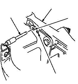
-5 RIG PIN
LATERAL
SERVOCYLINDER
BELLCRANK
LEVEL SWASHPLATE
RIG PIN HOLE
MID TRAVEL
RIG PIN HOLE
M70-147A
Figure 11–73.
Lateral Servocylinder Bellcrank
Task
Result
c. Move pilot cyclic stick to longitudinal mid
travel position. Install -9 rig pin in cyclic stick
housing cover longitudinal rig pin hole
(fig. 11–74).
d. In CPG cyclic stick housing cover
longitudinal rig pin hole (fig. 11–74), install
-11 rig pin.
If rig pin cannot be installed, perform lower
longitudinal flight control rigging between pilot and
CPG cyclic sticks (TM 1-1520-238-23).
e. In longitudinal servocylinder bellcrank mid
travel pin hole (fig. 11–75), install – 5 rig pin.
If rig pin cannot be installed, perform lower
longitudinal flight control rigging between pilot cyclic
stick and longitudinal servocylinder bellcrank
(TM 1-1520-238-23).
f. On longitudinal servocylinder, verify that
lower lever is aligned with upper edge of
boss on servocylinder body (fig. 11–76).
If lower lever is not aligned with upper edge of boss,
rig longitudinal flight controls between pilot cyclic stick
and longitudinal servocylinder (TM 1-1520-238-23).
g. Remove rig pins installed in steps c. through
e. Move pilot cyclic stick to align ZERO
CYCLIC LONG indicators (fig. 11–74). In
longitudinal servocylinder bellcrank level
swashplate rig pin hole, install -5 rig pin.
h. On mast base (fig. 11–77), install main rotor
rigging plate (TM 1-1520-238-23).