TM 1-1520-238-T-7
11–142
11–20. LONGITUDINAL (CYCLIC) FLIGHT CONTROLS – RIGGING OPERATIONAL
11–20
CHECK (cont)
ALIGNMENT TOOL
CENTER POINT
BASIC DIM
POINTER
MAIN ROTOR
RIGGING PLATE
MAIN ROTOR
RIGGING
FIXTURE
LATERAL
BELLCRANK
M70-152A
CENTERMARK
MAST BASE
LONGITUDINAL
BELLCRANK
AFT BOLTHEAD
ALIGNMENT TOOL
BASIC DIM
POINTER
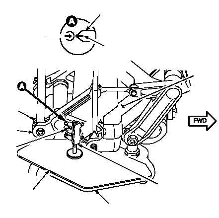
Figure 11–78.
Cyclic Long Zero Check
Task
Result
j. In head of longitudinal bellcrank aft bolt
(fig. 11–79), install alignment tool. Place
rigging fixture on rigging plate next to
alignment tool. Verify that BASIC DIM
pointer on rigging fixture aligns with center
point on alignment tool.
If BASIC DIM pointer on rigging fixture does not align
with center point of alignment tool, rig upper
longitudinal flight controls (TM 1-1520-238-23).
k. Remove -5 rig pin installed in step g.
l. Move pilot cyclic stick forward until it
contacts stop. Position rigging fixture to
align longitudinal FWD pointer with center
point of alignment tool. Verify that center
point of alignment tool is between the MAX
and MIN marks on rigging fixture
longitudinal FWD pointer (fig. 11–79).
If center point of alignment tool lies outside the MAX
and MIN marks on rigging fixture longitudinal FWD
pointer, perform rigging of longitudinal cyclic stick
stops (TM 1-1520-238-23).
If cyclic stick stops are rigged correctly, replace
longitudinal servocylinder (TM 1-1520-238-23).