
TB 1-1520-238-20-77
9. Correction Procedures.
a. Safe Helicopter per paragraph 1.57 of reference 13.a.
NOTE
To prevent unnecessary damage to screw, use of proper procedures and tools is
required during removal of tip cap. After removing tip cap screws, visually inspect
for any cracks, thread damage, obvious wear or physical damage. Apply thread
anti-seize compound, MIL-T-83483, to screw threads before reinstalling tip cap.
b. Remove main rotor blade leading edge tip cap per paragraph 5.13 of reference 13.a. Retain all
undamaged screws for reuse during re-assembly. Replace all damaged screws using standard ordering
procedures.
NOTE
Task is to be completed for each individual weight assembly before beginning task
on next weight assembly. Visually inspect studs for cracks, thread damage,
obvious wear, or physical damage. Do not remove weights from blade assembly.
c. Remove the two (2) nuts (MS21042-6) that secure the aft weight support fitting and discard. Apply
corrosion preventative compound (CPC) MIL-C-16173, Class 1, Grade 2 (soft film) to the threaded as well as
shank portion of both AFT studs during assembly. Reuse the existing washers (AN960C616L). Install two (2)
new nuts (NAS1 291 C6M) listed in paragraph 10 and torque the nuts to 205-225 inch-pounds. Use torque
wrench.
d. Remove the three (3) nuts (MS21042L5) that secure the forward weight support fitting and discard.
Apply corrosion preventative compound (CPC) MIL-C-16173, Class 1, Grade 2 (soft film) to the threaded as
well as shank portion of the three FWD studs during assembly. Reuse the two (2) existing washers
(AN960C516L) and the one (1) washer (HS5415-0001) on the leading edge stud. Position the HS5415-0001
washer to match the contour of the leading edge. Install three (3) new nuts (NAS1291 C5M) listed in paragraph
NOTE
The HS541 5-0001 washer may be trimmed, if necessary, to match the contour of
the leading edge. This is to ensure proper fit of the leading edge tip cap.
e. Reinstall the leading edge tip cap per paragraph 5.13 of reference 13.a.
10. Supply/Pans and Disposition.
a. Parts Required.
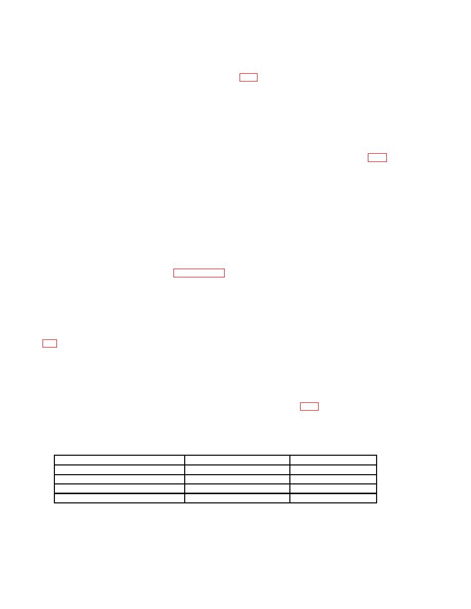
NOMENCLATURE
PART NUMBER
NSN
Nut, Self-Locking, AFT Fitting
NAS1291 C6M
Nut, Self-Locking, FWD Fitting
NAS1291C5M
Screw, Close Tolerance
HS4396-3T4
Screw, Close Tolerance
HS4396-3T5
5305-01 -219-8718
b. Requisitioning Instructions. Requisition replacement parts through normal supply channels using
normal supply procedures. All requisitions shall use project code " XB8 " per this TB.
3
