TB 1-1520-238-30-19
NOTE
Prior to cleaning, record all identifying marks that could be removed by the
cleaning and/or repairing process. Examine all parts and assemblies for
signs of scoring, burning or other defects. Note physical conditions that will
not be apparent after cleaning. Tag involved parts before they are cleaned
and laid out for detail inspection.
NOTE
Refer to figure 1 for the location of all clutch components. Refer to the web
site www.https//ams14.redstone.army.mil/safety/sof/pic/a6450401.pdf for
pictures of critical inspection and assembly steps.
NOTE
Discard all removed self-locking nuts at time of disassembly.
NOTE
Place parts on workbench, in order of disassembly in preparation for clean-
ing and inspection. Keep hardware and small parts together in trays or bas-
kets.
NOTE
During disassembly, parts may be cleaned of excess oil or grease, and
soiled areas may be removed using a clean, lint free cloth. Flange areas
and sealing surfaces shall be cleaned of excess oil, gasket material and
sealing compounds. Remove adherent gaskets(s) or sealing compound
residues using isopropyl alcohol or thinner. Clean out friction disk debris
from output housing (26) and splined output adapter (19). Parts should then
be set aside for inspection per Section 9.
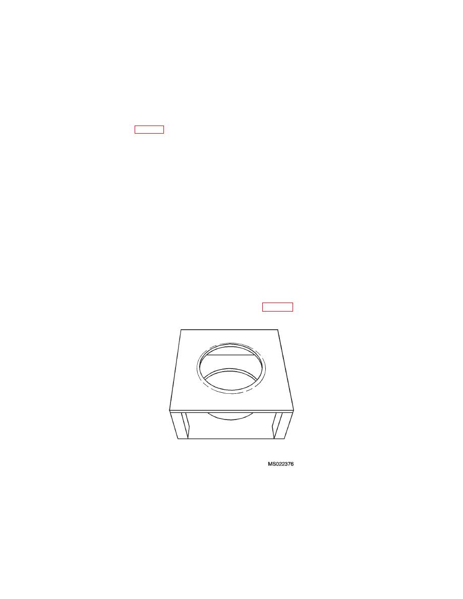
7.1 Place clutch assembly on holding fixture (P/N 296844-1, Figure 2) with input section down.
Figure 2. P/N 296844-1 Holding Fixture
7.2 Remove screws (1), washers (2), data plate (3), and gasket (4) - retain for reinstallation.
7.3 Remove bolt (8), washer (9) and ground strap terminal (10) - retain for reinstallation.
7.4 Remove nuts (5) and bolts (7). Discard nuts (5). Retain bolts (7) for reinstallation.
7.5 Remove nut (5) and bolt (6) at small identification plate. Discard nut (5). Retain bolt (6) for reinstallation.
6


