TM 1-1520-238-10
Change 4
4-5
Table 4-1.
Flight Symbology Definitions – continued
Fig. 4-1
Ref No.
Description
Symbol Name
21
Rocket Steering
Cursor
Indicates the required orientation to align the helicopter into constraints for
2.75 inch FFAR rocket engagements. During fixed or flight stow rocket
delivery, a broken I beam will appear.
22
Hover Position Box
Displays helicopter relative position when bob-up mode is selected and
represents an 8 foot square. Maximum displacement is 48 feet laterally or
longitudinally. The Hover Position Box drifts while in a stationary hover.
A drift of 6 feet the first minute is possible, and as much as 23 feet after 5
minutes when using EGI with GPS keyed tracking 4 or more satellites. If
these conditions are not met, a drift of 21 feet per minute is possible.
23
Head Tracker
Indicates the pilot head position relative to the center line of the helicopter.
This is a virtual symbol whose range of display is 30 degrees vertically and
40 degrees horizontally about the nose of the helicopter. When CPG selects
PLT/GND ORIDE and SIGHT SEL NVS, this symbol indicates his head
position.
24
Airspeed
A digital display of true airspeed when the ADSS is turned on or not failed. If
the ADSS is OFF or failed, display is ground speed in knots from the doppler
navigation system. Range is 0 to 200, omnidirectional.
25
Horizon Line
Indicates pitch and roll attitude of the helicopter.
26
Engine Torque
Indicates the engine torque output by the engines. The magnitude is the
larger of the two engine torque values. If a greater than 12% torque split
occurs between engines, the displayed torque value will flash. At an engine
torque value of 98% or higher, a box around the torque value flashes to
indicate an impending engine torque limit. Symbolic torque value maximum
is 120%.
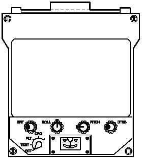
4.4 VIDEO DISPLAY UNIT (VDU).
The VDU (fig 4-2) is located in the pilot vertical instrument
panel (fig 2-9). The basic configuration has a red night fil-
ter which is stored in a bracket on top of the unit. The -3
configuration VDU has a gray night filter which is stored in
a protective pouch on top of the unit. The red and gray fil-
ters are used on evening and night flights to provide a dis-
play which does not affect the pilot night vision. The VDU
has the capability of displaying the video from either the
pilot or CPG selected sensors independent of the
IHADSS. This permits the pilot to have a simultaneous
display of the PNVS video on the HMD and CPG video on
the VDU. In the event of pilot HDU failure, a limited night
terrain flight capability is available by selecting PLT on the
VDU and placing the PNVS in the NVS FXD position. The
VDU receives 28 vdc power from the No. 2 essential dc
bus and is protected by the VDU circuit breaker located on
the pilot overhead circuit breaker panel. The VDU is not
monitored by FD/LS. The function of each switch is de-
scribed in table 4-2.
M01-023
Figure 4-2.
Video Display Unit