TM 1-1520-238-10
4-6
Table 4-2.
Video Display Unit Control/Indicator Functions
Switch/
Control
Position
Function
OFF
Removes all power to the VDU.
TEST
Displays a vertically oriented test pattern.
PLT
Displays pilot selected video.
CPG
Displays CPG selected video.
BRT
Adjusts display brightness.
ROLL
Adjusts roll trim on the symbolic horizon displayed in the transition and cruise modes
of flight symbology.
PITCH
Adjusts the pitch trim on the symbolic horizon displayed in the transition and cruise
modes of flight symbology.
CTRS
Adjusts display contrast in PLT and CPG modes.
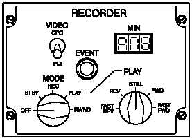
4.5 VIDEO RECORDER SUBSYSTEM (VRS).
The VRS consists of an airborne video recorder, located in
the left side of the aft avionics bay (fig 2-2), and the video
recorder control panel, placarded RECORDER (fig 4-3),
located in the CPG left console (fig 2-12). The VRS has
the capability of recording up to 72 minutes of either pilot
or CPG selected video. Capability exists for playback on-
board the helicopter for real time damage assessment
and reconnaissance. The VRS receives 115 vac from the
No. 2 essential ac bus through the RCDR circuit breaker
on the CPG No.1 circuit breaker panel. The VRS is not
monitored by FD/LS. The video tape recorded onboard
the helicopter requires a special video playback unit to
view the imagery off the helicopter. The video recorder
control panel control/indicator functions are discribed in
table 4-3.
M01-185
Figure 4-3.
Video Recorder Subsystem Control
Panel