TM 1-1520-238-10
4-73
4.37.3 AN/APR-39(V)1 Operation Modes.
The RW set
may be operated in either the discriminator off or discrimi-
nator on mode. The RW set receives 28 vdc from the
emergency dc bus through the RDR WARN circuit break-
er on the pilot overhead circuit breaker panel. The RW set
is not monitored by FD/LS.
NOTE
Display strobe lengths indicate only relative
signal amplitude. Since many variables can
affect the atmospheric attenuation of the
signals, strobe length should not be consid-
ered as a direct interpretation of the dis-
tance to the emitter.
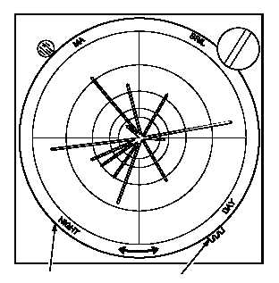
a. Discriminator Off Mode.
When operating in the
discriminator off mode, the DSCRM switch is placed to
OFF. In this mode all high band received signals with am-
plitude greater than a predetermined threshold level are
displayed on the CRT and an audio signal, representative
of the combined amplitudes and pulse repetition frequen-
cies (PRF), is present at the headset. The displays indi-
cate the total radar environment in which the helicopter is
operating. Each radial strobe on the CRT is a line of bear-
ing to an active emitter. When a SAM radar complex be-
comes a threat to the helicopter (low band signals corre-
lated with high band signals), the alarm audio is
superimposed on the PRF audio signal and the MA light
and associated strobe start flashing. Lengths of strobes
and audio levels depend on the relative strength of the in-
tercepted signals. A typical display when operating in the
discriminator off mode is shown in figure 4-21.
NOTE
In this mode, received low band signals
which are not correlated with a high band in-
tercept will cause the MA light to flash and
an alarm audio will sound.
b. Discriminator On Mode.
When operating in the
discriminator on mode, the DSCRM switch is set to ON. In
this mode, signals are processed to determine their con-
formance to certain threat associated criteria as follows:
(1) The signal level must be greater than the mini-
mum threshold level.
(2) Pulse width must be less than the maximum
pulse width.
FILTER
FILTER
CONTROL
M01-186
Figure 4-21.
Radar Warning Discriminator Off
Mode Display
(3) PRF must be greater than the minimum pulses
per second.
(4) The pulse train must exist with not less than the
minimum pulse train persistence.
The CRT display is divided into eight sectors. Strobes are
displayed only in those sectors in which signals meeting
all threat criteria are present. This reduces display clutter
by eliminating low-level and wide pulse width signals and
by selective sector display. Intercepts which meet these
requirements are displayed as described in paragraph
4.37.3 a.
NOTE
In this mode, uncorrelated low band signals
will not give any indications.
A typical display when operating in the discriminator ON
mode is shown in figure 4-22. Conditions are the same as
for figure 4-21, but it is assumed that one or more threats
have been identified in the 225 to 270 degree sector.