TM 1-1520-238-23
1-118
1.36.
UTILITY HYDRAULIC ACCUMULATOR SERVICING – NITROGEN – continued
CAUTION
This chart is for use on aircraft equipped
with winterization kit only.
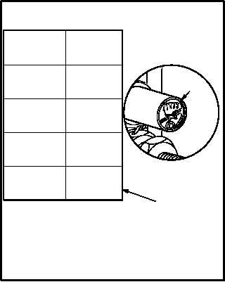
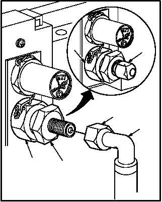
l. Service utility hydraulic accumulator accord-
ing to specifications in chart (14).
(1) Loosen nut (10) until resistance is felt; then
loosen 1/2 to 3/4 turn to off seat valve.
(2) Select correct pressure from chart (14) ac-
cording to temperature.
(3) Tighten nut (10) when gage (13) reads cor-
rect pressure.
NOTE
Allow pressure to stabilize 5 minutes. Ad-
just pressure if necessary.
m. Disconnect nitrogen truck service hose (7)
from valve (8). Torque nut (10) to 60 INCH-
POUNDS.
(1) Remove nitrogen pressure.
(2) Hold valve (8). Remove nut (11).
(3) Torque nut (10) to 60 INCH-POUNDS. Use
torque wrench.
(4) Install cap (9) on valve (8).
n. Inspect (QA).
o. Service utility hydraulic system with fluid
(para 1.34).
p. Secure access door R325 (para 2.2).
END OF TASK
M04-1621-10
1577 - 1615
1653 - 1691
1615 - 1653
1691 - 1729
1767 - 1805
1729 - 1767
1805 - 1843
+45 TO +55
1843 - 1881
+55 TO +65
+35 TO +45
+65 TO +75
1881 - 1919
1919 - 1957
1957 - 1995
1995 - 2083
+25 TO +35
+15 TO +25
+5 TO +15
-5 TO +5
-15 TO -5
-25 TO -15
-35 TO -25
-45 TO -35
13
14
OUTSIDE
AIR
TEMPERATURE
(ºF)
NITROGEN
PRESSURE
(psig)
9
8
11
7
10
8
M04-1621-2