TM 1-1520-238-23
3-132
Change 9
3.38.
TAIL LANDING GEAR SHOCK STRUT REMOVAL/INSTALLATION – continued
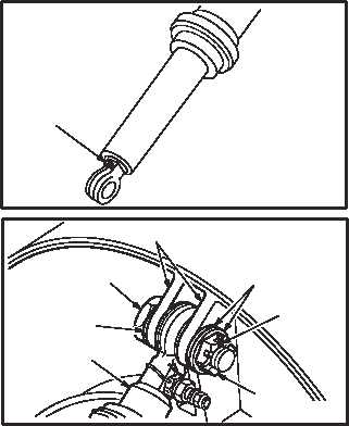
e. Check shock strut housing for dents, nicks, or
scratches.
(1) Maximum allowable depth is 0.020 INCH.
Blend out any nicks, dents, and scratches.
f. Check shock strut piston polished surfaces
for nicks, dents, or scratches. None allowed.
g. Check shock strut for corrosion (para 1.49).
NOTE
Ensure pneumatic valve (22) is facing the
right hand side of aircraft.
3.38.6. Installation
a. Install strut (1) on lugs (16). Torque nut (19) 400
to 440 INCH-POUNDS.
(1) Position strut (1) between lugs (16).
(2) Install bolt (18) with washer (21).
(3) Install two washers (20) and nut (19). Torque
nut (19) to 400 INCH-POUNDS. Use torque
wrench.
(4) Increase torque to aline cotter pin holes, but
do not exceed 440 INCH-POUNDS.
(5) Install new cotter pin (17).
b. Inspect (QA).
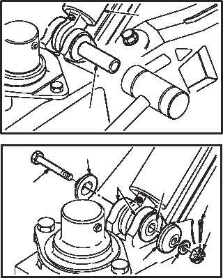
c. Install strut (1) on arm and socket lugs (8).
(1) Position strut (1) between lugs (8).
(2) Install pin (15) through strut (1) and lugs (8).
Use mallet.
(3) Install bolt (10) with cap (14) through pin (15),
cap (13), and washer (12).
(4) Install nut (11) and new cotter pin (9).
GO TO NEXT PAGE
22
M04-035-12
1
M04–035–11
17
19
21
18
16
20
M04–035–8A
1
15
M04-035-9A
10
14
9
11
13
15
12
8