TM 1-1520-238-23
3-225
3.59.
PARKING BRAKE PULL CONTROL ASSEMBLY AND BRACKET ASSEMBLY
REMOVAL/INSTALLATION – continued
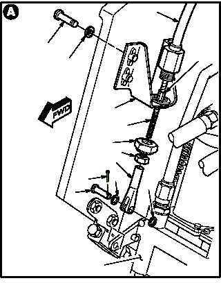
b. Remove pull control assembly (1) from rotary
direct valve (2).
(1) Loosen nut (3).
(2) Remove and discard cotter pin (4).
(3) Remove straight head pin (5) and two wash-
ers (6).
(4) Remove clevis (7) and nut (3) from cable (8).
(5) Remove control assembly (1) from valve (2).
c. Remove bracket assembly (9) from center
console panel (10).
(1) Hold cable (8) at hex swage (11). Remove nut
(12).
(2) Slide cable (8) from bracket (9).
(3) Remove four screws (13) and washers (14)
from bracket (9).
(4) Remove bracket (9) from console (10).
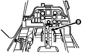
d. Enter pilot station (para 1.56). Observe all
safety precautions.
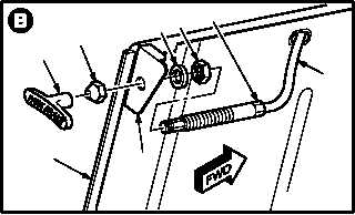
e. Remove handle (15) from control assembly
(1).
(1) Remove handle (15) from control assembly
(1).
(2) Remove seal nut (16).
(3) Remove cable (8) from angle (17).
(4) Hold cable (8) at hex swage (11). Remove nut
(18) and washer (19).
f. Remove cable (8) from console (10).
GO TO NEXT PAGE
13
14
9
8
12
6
7
3
4
5
6
M04-2680-2
2
11
1
PILOT STATION
M04-2680-7
15
16
1918
11
8
17
10
M04-2680-3