TM 1-1520-238-23
3-227
3.59.
PARKING BRAKE PULL CONTROL ASSEMBLY AND BRACKET ASSEMBLY
REMOVAL/INSTALLATION – continued
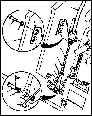
d. Install bracket (9) on cable (8).
(1) Insert cable (8) clevis end through hole in
bracket (9). Install nut (12).
(2) Hold cable (8) at hex swage (11). Tighten nut
(12).
(3) Install four screws (13) through washers (14)
and console (10) into bracket (9).
e. Install control assembly (1) on valve (2).
(1) Install nut (3) and clevis (7) on cable (8).
(2) Adjust clevis (7) and nut (3).
NOTE
Valve lever must be in full down position.
(3) Remove slack from cable (8).
(4) Aline clevis (7) holes with lever (20) hole.
Tighten nut (3).
(5) Insert pin (5) through washer (6), clevis (7),
lever (20), and washer (6).
(6) Install new cotter pin (4) in pin (5).
f. Enter pilot station (para 1.56). Observe all
safety precautions.
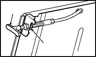
g. Tighten nut (18).
(1) Hold handle (15). Tighten nut (18).
h. Inspect (QA).
i. Secure CPG seat (para 2.161).
j. Set parking brakes (para 1.61).
END OF TASK
13
14
10
9
4
6
5
6
20
1
7
M04-2680-5
3
11
12
8
15
18
M04-2680-4
P
AR
K
BRAKE


