TM 1-1520-238-23
2-306
Change 1
2.88.
ROTOR SUPPORT MAST SUPPORT BASE REMOVAL/INSTALLATION – continued
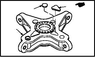
e. Clean sealing compound from top of four cov-
ers (11) and (12) (para 1.47).
f. Remove and discard four covers (11) and (12)
from mast base (1).
2.88.4. Cleaning
a. Remove adhesive from mast base and light-
ening holes. Use cloth (item 47, App F).
b. Clean mast base and lightening holes (para
1.47).
c. Remove paint from lightening holes
(TM 55-1500-345-23).
2.88.5. Inspection
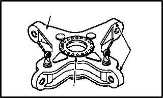
a. Check mast base and transmission struts for
cracks. None allowed.
b. Check mast base and transmission struts for
nicks, scratches, and gouges.
(1) Acceptable without rework: nicks, scratches,
and gouges that do not penetrate surface
protective finish.
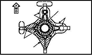
(2) Rework for nicks and gouges: maximum al-
lowable depth for zone 1 is 0.070 INCH; zone
2 is 0.050 INCH; and zone 3 is 0.007 INCH.
c. Check mast base for corrosion (para 1.49).
(1) Maximum allowable depth for zone 1 (all
areas not specified) is 0.015 INCH; zone 2
(upper and lower flanges, and tapered ends)
is 0.050 INCH; zone 3 (mast bolt circle) is
0.005 INCH; and zone 4 (lug ends) is 0.150
INCH.
d. Check walls and bottom area of lightening
holes for dirt, fluid, and debris. None allowed.
Use flashlight and mirror.
GO TO NEXT PAGE
M04-3086-8A
11
12
1
M04-3086-9
ZONE 1
ZONE 2
ZONE 3
ZONE 3
ZONE 1
ZONE 1
ZONE 2
ZONE 4
M04-3086-12
ZONE 1
ZONE 4