TM 1-1520-238-23
2-350.8
Change 2
2.95A.
LEFT HAND OR RIGHT HAND LONGERON REMOVAL/INSTALLATION – continued
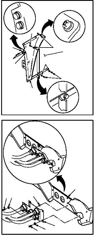
i. Install fairing (3) on firewall (4).
(1) Aline fairing (3) on firewall (4).
(2) Install two screws (5) through washers (6)
and fairing (3) in firewall (4).
(3) Install four bolts (7) through washers (8) and
fairing (3) in firewall (4).
j. Install data link bracket (24) on longeron (12).
(1) Aline bracket (24) on longeron (12).
(2) Install screw (27) through washer (28), brack-
et (24), and spacer (29) in longeron (12).
(3) Install three screws (25) through washers
(26) and bracket (24) in longeron (12).
k. Perform electrical bond check on attaching
parts (TM 55-1500-323-24).
(1) Bond shall be 0.1 ohm or less. Use
multimeter.
l. Seal edge of bracket (24) and longeron (12).
Use sealing compound (item 176, App F) and
spatula set.
GO TO NEXT PAGE
7
7
8
5
6
4
8
3
8
M04-5105-17
24
25
26
29
27
28
12
M04-5105-18

