TM 1-1520-238-23
5-266
Change 9
5.61.
TAIL ROTOR HEAD INSTALLATION – continued
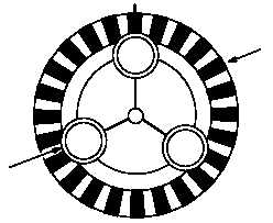
a. Locate and mark the #1 mounting stud (3) on
shaft (2) with an ”X”. The #1 mounting stud (3)
is located counter–clockwise from the #2
mounting stud which is the only stud that is
aligned with a gear tooth. Use torque stripe
paint.
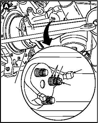
b. Install tail rotor head (1) on tail rotor gearbox
output shaft (2) with mounting stud (3)
marked with torque stripe painted ‘‘X” adja-
cent to arm of teeter stop (4). Torque three nuts
750 INCH–POUNDS (5) to (after MWO
1-1520-238-50-46). Use maintenance platform.
(1) Apply corrosion preventive compound
(item 62, App F) to studs (3).
(2) Install head (1) on shaft (2) with mounting
holes alined.
(3) Install six washers (6), two on each stud (3).
(4) Install three new nuts (5).
NOTE
Torque is equal to run-on torque plus
torque value given.
(5) Torque three nuts (5) to 750 INCH-POUNDS
(before MWO 1-1520-238-50-46) or 710 IN-
CH-POUNDS
(5) (after MWO 1-1520-238-50-46). Use torque
wrench and torque wrench adapter.
c. Check that each nut (5) has 2-1/2 stud threads
showing.
(1) If not, remove one washer and repeat steps
b.(4) and b.(5).
d. Apply primer to nuts (5), washers (6), and ex-
posed threads of studs (3). Use epoxy primer
coating kit (item 78, App F).
GO TO NEXT PAGE
M04–3882–6
3
2
1
SPLINE
TEETH
ON CENTER
3
M04–262–2B
1
65
3
2
4
6.
1


