TM 1-1520-238-23
Change 7
5-266.1
5.61.
TAIL ROTOR HEAD INSTALLATION – continued
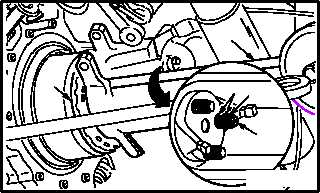
e. Apply corrosion preventive compound to the
curvic coupling interface (6.1) with the head
(1) to seal the curvic teeth. Use corrosion
preventive compound (item 62A, App F).
f. Apply a slippage mark across each stackup to
include the stud (3), nut (5), washer (6), and
the head (1).
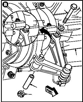
g. Install two drive links (7) on head (1). Torque
two nuts (8) 30 to 40 INCH-POUNDS.
(1) Position two links (7) between lugs of each
clevis (9).
(2) Install two bushings (10) through clevis (9)
and two links (7).
NOTE
Washer must always be installed on the
side of the clevis with the small hole.
(3) Install two bolts (11) and washers (12) with
heads of both bolts (11) facing direction of
rotation.
(4) Install two new nuts (8).
(5) Hold two bolts (11). Torque nuts (8) to 30
INCH-POUNDS. Use torque wrench.
(6) Increase torque to aline cotter pin hole, but do
not exceed 40 INCH-POUNDS.
(7) Install new cotter pin (13).
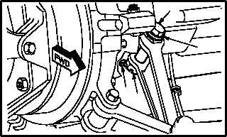
h. Apply primer to heads of bolts (11), washers
(12), nuts (8), exposed threads of bolts (11),
and cotter pins (13). Use epoxy primer coating
kit (item 78, App F).
GO TO NEXT PAGE
1
6.1
65
3
M04-262-5
M04-262-3
7
1
10
8
11
12
9
M04-262-6
138
11
12